So…. part two! Well its now March 2024, and I’m still working on this project. No it isn’t built yet, I know, you’re asking what the heck am I playing at? Believe me, I’m as shocked as you are, with how much time has passed. I can’t believe this all started back in June 2021, when I got that message about the old C11 telescope in the observatory in Dundonald! When I left you last, we had just poured the concrete for the pier, well good news, it’s now set! That was August 2022! So where am I now? Well, let me take you on the journey and bring you all bang up to date!
Back indoors to the dome construction. So you may remember from my CAD design drawing that I was making the frame out of 12mm plywood, doubled up so the thickness was 24mm. I used various 90 degree and hinged brackets to hold the frame in the required position.
I completed one half of the dome frame as I now realised that if I was to build the complete dome in my shed I wouldn’t be able to get it out the door, I’ll come back to that one! Now, next problem, how to fill in the area between the frame (the shell)!
My solution, recycled steel barrels cut into sections to make up a trapezium dome!
Now that would be simple wouldn’t it? One line doesn’t really demonstrate the time and effort required to get to that solution, want to know why this project has taken so long, well this is one of the reasons. If you remember in part one, Mark Parrish, who I based this design on, used plywood to make the shell of his dome. He managed to basically steam large sheets of plywood and form the dome curves from these, he then used a fibre glass mix to waterproof the shell. This is where his design and my design of dome part company, my dome is a lot larger than his and getting big enough sheets of plywood and being able to steam them to shape, (also the cost of the fibre glass mix) ruled this design out for me. Have you ever tried to bend semi rigid material one direction and then another at the same time (x and y axis)? Try it… its good fun! NOT! So I went from wood to plastic to metal, reason being my dad is a good welder, actually now so am I as I’m coming to the end of this project. So how do you bend metal in two directions at the same time? Basically, you don’t, it is virtually impossible without melting, heating, moulding and praying it works. No, that’s a stretch too far for me, enter the Trapezium dome. Basically you keep the metal straight/flat, but cut it into smaller sections that can be angled to make the shell of the dome. There’s even a calculator on the interweb to help you design it. Here’s how my calculations went:
So, now that I know what I need to do, what material? Facebook marketplace… straight sided recycled steel barrels from Tamnamore, Co.Tyrone. Don’t ask!
The barrels of Tamnamore
What 10 look like, when sliced down the middle and the bottoms removed
I should also say at this point, I made another design change. The ring on top of the observatory, that the dome would rotate on… well its now made of steel, not wood! I figured this part should be somewhat more substantial, as this was the part that the dome would be rotating on and would be carrying all the weight. I drew up the following design and went to a local machine shop to supply the steel and water cut it to my specification shown below.
As you can see in the drawing I decided on 6mm thickness. Now, it would be great if the company could have made this in one bit, but as you would expect it was too large and I wouldn’t have been able to transport it anyway, so it was made in 5 pieces. This would have to be joined later, I’ll come back to that!
Now, back to the dome shell. I showed you the trapezium design and the barrels, in the next picture you can see a test piece out of plastic which I tried out as a demo, one issue you may have already noticed… flat panels vs round drums, yes that would be an issue. Let me show you what we had to come up with to rectify that one.
Yes, we had to make a device to bend the drums straight. Made out of some old rollers that we fed the drums through to straighten them out. Mostly worked ok. Also instead of trying to weld straight edges of the trapezium together my dad decided we should fold all the edges so we could either weld them or bolt them together as required. So, yes we made a folding table… yeah that’s a singer sowing machine base its bolted onto. The dimensions of the trapezium sections were now increased to allow for the folded edges.
My dad started on this task at his home, you’ll see in the pictures that he used a couple of the ring sections to give him a guide for the angles of the dome.
Back to my place now to see what they look like on the wooden framework!
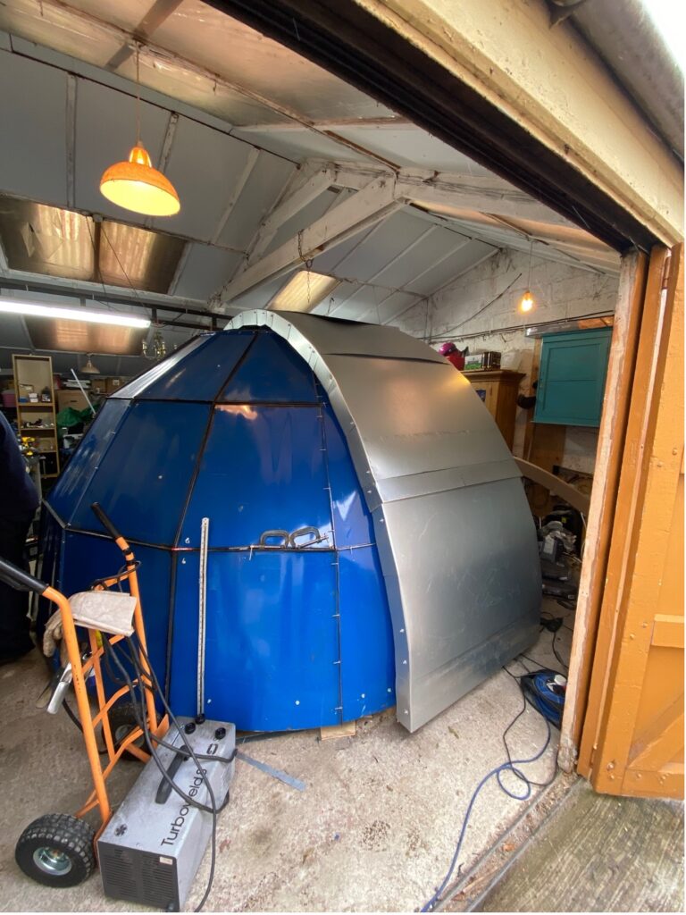
Not bad at all! We decided at this point that we needed to completely build the dome inside the shed. It would be too much work to do outside, and we would be working at height. Benefits: · working inside over bad weather · working at a reasonable height to get it built · able to design and overcome issues as they arise without having time constraints Issues: · How the heck can we get it out! I told you we would come back to that point So basically, we were going to have to build this inside, with the intention that it can and will be taken apart again to get it out the door, either that or we take the roof off and get a crane. We’ll just take it apart again… on the subject of cranes though, when we rebuild the dome, how am I going to get it onto the observatory? As I write this, that question is still to be answered!
I assembled the other half of the wooden dome frame and then put some wheels on, so the dome could be turned inside the shed to allow us access to work from one side. This worked well and as you can see in the photos, we now have two sides completed.
It was then time to move onto the centre dome shell and the shutter. Obviously the opening only needed to be slightly over half of the dome, so the rest could be closed in with more tin. At this point we started to run out of steel barrels so we had to purchase some sheets of galvanised steel. What a pleasant surprise it was to now be working with straight, new sheets, a lot easier to manage.
I needed to come up with something to let the shutter move on, and I was able to obtain some old/used conveyor guide rails from my work. The reverse side of the guide rails have a nice deep grove which would be ideal for small rollers to run on. These guides were installed full length on both sides of the shutter window.
We made up a test with rollers to see what way they moved on the guide rails.
They seems to work very well, so next step was to buy some angle iron and make up a frame for the shutter.
If you are familiar with dome shutters you will know that they don’t open right from the bottom of the dome. This is so that they can roll back right over the zenith to allow the telescope to point straight up. This then raises the question, how can the telescope see low in the horizon? Many solutions usually include a bottom section that can either be lifted out manually or hinged out as required. The hinged out variant was what I had intended, however when it came to designing and building this, it proved difficult. What was easy, was to just make a second roller shutter frame, that could be attached to the main shutter and roll up with it when required. This is what I did!
Time to add the shell to the shutters.
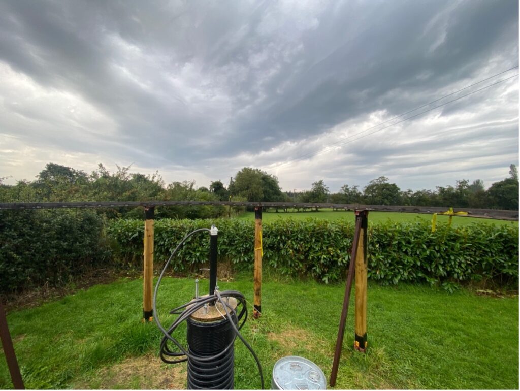
That’s all for the dome inside. Time to return to the observatory outside. Remember it looks like this:
Time to put the ring together… let’s get welding again!
Now, if you look at the ring on top of the posts, it looks warped. Well that’s because it was. I needed something to strengthen it and straighten it up. More welding required!
A lot better looking now. Not only straight, I also now have a rail that I can use to centre the dome on.
Next.. do we want to strengthen the posts and base, now that the dome has been built and we know it’s really heavy! Yeah, we better do something! Let’s get the cement mixer going again, yeah it got some loving over the last few months as well and is all fixed up and ready to go again!
Did someone say floor?
Door frame?
Other business going on in parallel: What’s in the box?
I’m very grateful to fellow NIAAS committee member Lawrence Hanna, who happened to have a Sky Watcher EQ8 mount getting in the way and has given me it to test out in the observatory!
Plaster scratch coat…. I must admit I didn’t really enjoy this bit. Hard on back and very messy!
Some pebbledash left over from house renovation. I’ll have some of that! Also, you’ll notice some more timber strengthening to the posts.
So, remember I said I enjoyed working with the nice new sheets of galvanised steel… well I do need some walls!
Let’s get the floor down! Time to recycle again… some decking boards reclaimed from a caravan park!
Some steps and a trapdoor to cover the steps when we are inside. Don’t want to fall down them in the dark, do we? Something else… a door… recycled of course!
Well, that brings me to the end of part 2. You’re right up to date now. Next stage coming up is of course getting the dome onto the observatory. I hope you are worried for me.. I know I am as I’m still not sure how I’m going to do it. In the meantime, I’ve been doing a ton of research into all sorts of lovely topics, dome automation, telescope control, lighting control and even planetarium projection. Yeah, this will be very special if I can pull it all off. I’m getting really excited now and I’m really enjoying every minute I get working on it with my dad. Special times! Until next time… hopefully part 3 won’t be too long coming and it should be the final part in this project, I’m looking forward to it, I hope you are too!
We use cookies to ensure that we give you the best experience on our website. If you continue to use this site we will assume that you are happy with it.